
1 Figure
A receiver counterpart to the small one-watt transmitter described in
               the March issue. By T. W. Dresser.


In a  recent  issue of  Practical  Wireless the  writer described the
"Cigar  Box  Transmitter,"  an  extremely  small  1  watt transmitter
suitable for the amateur  without mains electrical supplies or who is
so restricted for space that anything in the nature of a normal sized
shack and transmitter is entirely out of the question. In the present
article it  is proposed to  describe the receiver counterpart to that
transmitter,  an equally small unit which, despite its small size and
simple  circuit arrangement,  will  nevertheless  put up quite a good
show.

To begin  with,  those who  think only in terms of double conversion,
crystal filters, phasing controls and the other more elaborate gagets
of the  high-priced commercial receivers,  will not be  interested in
this  receiver.   None of  those  adornments can  be built into a TRF
amplifier,  leaky-grid detector,  with reaction and  audio amplifier.
All the  valves are of the same type, 1T4's, just as are those in the
transmitter.   The excellent performance arises principally from good
layout,  adequate screening and the very smooth regeneration provided
by potentiometer control on the screen grid of the detector.   It has
been called a cigar box receiver, and can easily be built into such a
box, as was the original, but there is no reason why it should not be
assembled in  a metal case or on a small  metal chassis, and, in some
cases,   this may  be  an advantage  in that  it helps  to keep  down
hand-capacity effects. These were not noticeable in the prototype, as
the cigar box was  completely lined with aluminium foil, which made a
most effective scree.

The form of construction used at the RF end may be rather unusual but
it has many advantages,  noticeably in  keeping grid  and anode leads
down to a minimum length  and  in isolating the  RF  stage  from  the
detector as far as unwanted  interaction  was  concerned.   Nor is it
difficult to build as the screen can be removed from the box,  the RF
valveholder  and  the  detector grid coil holder  fitted and wired to
some extent before it is permanently  fastened  into position.   This
greatly facilitates construction.

As originally built, the receiver covered the five main amateur bands
3.5 7, 14, 20 and 30 Mc/s, using a ganged 15pf funing condenser. With
some small changes it can be made to cover 3.5 - 30 Mc/s continuously
and the  coil data  and all necessary information is given  for  both
coverages.

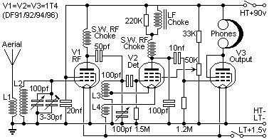
The theoretical diagram is given in Fig. 1  and
it will be  noted that the  reaction is  controlled  by  varying  the
screen-grid voltage,  a method which  has a lot in its favour in that
it does not affect the tuning to any noticeable degree.  The detector
anode load is a high-inductance  LF choke of some hundreds of Henries
and  that  used  by  the  writer  was  a  pre-war  component.   It is
questionable  whether  such  a  choke  can be obtained today, but the
primary  winding  of an  ordinary inter-valve transformer  will serve
just as  well  (I used a 28v PCB relay - Harry).   In that case,  the
secondary  can be  left  disconnected or  placed in  series with  the
primary, but care must be taken to see that it is truly in series and
not  connected in such a way that  it reduces the  inductance of  the
primary,  which can happen.   As with its companion transmitter,  all
components  should  be  as  small  as  possible  consistent with good
quality.

Figure 2
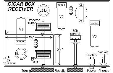
Figure 2 shows the lay-out of the receiver.  The
cigar box is lined with thin completely flat and unwrinkled aluminium
foil, pressed well down at all corners and fastened round the edge of
the box  with drawing pins  or strips of aluminium screwed down.  The
screens are then cut and bent from sheet aluminium as shown in Fig. 2
(CIGAR-TM.GIF - Harry),  and the  RF  valveholder  and  detector grid
goil-holder mounted as shown.   The screen can then be screwed inside
the box with very small brass wood screws of no more than 3/16in.  or
1/4in. in length.  The remainder  of the construction  and the wiring
are quite straightforward and if the diagrams are followed carefully,
there is little  likelihood of error.   As with any other  short-wave
receiver  all  wiring should  be as short  as possible,  and a common
earthing point should be used for each stage.  Coil formers should be
of good  quality material,  such as polystyrene,  and the tuning gang
(or coupled condensers) should preferably have ceramic insulation.

The only  difference between the amateur  band version,  and that for
3.5 - 30 Mc/s continuous coverage are in the size of the coil formers
and  the  sockets  for them,  and  in  the  capacity  of  the  tuning
condensers.   In the first mentioned the coil formers are Maxi-Q dust
cored 5-pin types, with holders to suit,  and the tuning condenser is
a 2-gang 15pf variable or two separate 15pf coupled together.  In the
continuous coverage version the tuning condenser is a two-gang 100 pf
variable,  and the coil formers are standard 1-1/4in. 5-pintypes with
sockets  to match.   The change in the mechanical  layout is so small
that it needs no detailed description.

As the interior of the cigar box is completely covered with aluminium
fail,  it is advisable  to keep a close eye on connections and wiring
generally in order that they may not earth to the foil.   Where there
is  a  danger  of  this a small  piece of cardboard  or  fibre  under
valveholders and at  strategic points will eliminate the danger.   As
with all TRF receivers, a good aerial  is half  the  battle.   If the
receiver is to be used with the cigar box transmitter the same aerial
will serve both;  a  simple  form  of switching  will change over the
batteries and the aerial from transmitter to receiver simultaneously.
If the receiver is to be used alone, an aerial as high and as long as
possible should be erected.

In conclusion,  the quiet  background and signal getting qualities of
this little set will prove a pleasant surprise to those accustomed to
elaborate AC types, and, at the same time, its cheapness is such that
even the beginner need not remain without a short-wave receiver if he
has the pound or two necessary to build it.

          Coil data  for 3.5 to 30 Mc/s continuous coverage
Band      L1             L2             L3      Tap L3       L4
====  ==========    ===========    ===========   ====    ============
 1    6 turns 28    25 turns 28    25 turns 28     4     4 turns 28
      swg enamel    swg enamel     swg enamel            swg enamel
====  ==========    ===========    ===========   ====    ============
 2    5 turns 28    14 turns 28    14 turns 28     3     3 turns 28
      swg enamel    swg enamel     swg enamel            swg enamel
====  ==========    ===========    ===========   ====    ============
 3    3 turns 28    6 turns 28     6 turns 28    2.5     2.5 turns 28
      swg enamel    swg enamel     swg enamel            swg enamel
====  ==========    ===========    ===========   ====    ============


                   Coil data  for amateur bands
Band      L1             L2             L3      Tap L3       L4
====  ==========    ===========    ===========   ====    ============
3.5-  7 turns 28    60 turns       60 turns       10      10 turns
4.0                 closewound     closewound
====  ==========    ===========    ===========   ====    ============
6.9-  5 turns       30 turns       30 turns        5       5 turns
7.4                 closewound     closewound
====  ==========    ===========    ===========   ====    ============
13.9  3 turns       20 turns       20 turns      3.5     3.5 turns
14.4                 spaced 1/2"    spaced 1/2"
====  ==========    ===========    ===========   ====    ============
20.5  3 turns       13 turns       13 turns        3       3 turns
22.0                spaced 1/2"    spaced 1/2"
====  ==========    ===========    ===========   ====    ============
27.0  2 turns       10 turns       10 turns        3       3 turns
30.0                spaced 1/2"    spaced 1/2"
====  ==========    ===========    ===========   ====    ============
Have fun, de HARRY, SM0VPO Upplands Vasby, Sweden
Frank, G3YCC